Introduction
The wind direction is measured with a wind vane and indicates the direction from which the wind is blowing. It is determined by the polar angle (azimuth) on the 360-degree scale, relative to geographic north (east = 90°, south = 180°, west = 270°, north = 360°). In practice, the 8-point compass rose is mostly used (N, NE, E, SE, S, SW, W, NW).
In the smart home, wind direction plays a rather minor role – but it is part of complete weather data recording.
Available measurements
| Variable | Unit | Source | Description |
|---|---|---|---|
| winddir | ° | Measurement | Wind direction |
| winddir_avg10m | ° | Measurement | Avg. wind direction last 10 min. |
| winddir_avg2m | ° | Measurement | Avg. wind direction last 2 min. |
Sensor used
We use the high-quality aluminium wind vane from ComWinTop/Renke (CWT-SWD-A-360-A) with analog 0-5 V output and continuous 360° measurement. The build quality is very high: aluminium housing, completely protected against moisture by O-ring seals in the housing and connector. The angle is determined contactlessly via a Hall angle sensor (magnet on the shaft above the sensor IC), which speaks for a long service life. The output voltage is linearly assigned to the angle (0 V = 0°, 5 V = 359.9°) and is read via the ADS1115 analogue-to-digital converter of the control unit.
Datasheet
Specification
- Measuring range: 360° (continuous)
- Accuracy: ±1°
- Output: 0-5 V (analog)
- Supply voltage: DC 10-30 V
- Power consumption: ≤ 0.2 W
- Response time: ≤ 0.8 s
- Operating range: −20 … +60 °C / 0-80 % RH
- Dimensions: width 246 mm, height 201.5 mm
Parts list
Available as a kit
All necessary components of this guide are also available as a complete kit! The kit contains all individual components (except adhesives, solder, etc.) – including the required PCBs and 3D printed parts. With your purchase you also support us in the further development of the DIY weather station.
Request a kit ›| Quantity | Component | Source |
|---|---|---|
| 1 pc. | ComWinTop / Renke wind direction sensor (aluminium, analog 0-5 V, 360°), CWT-SWD-A-360-A | Ali Express / Amazon |
| 1 pc. | 3D printed adapter / housing wind sensor | see below |
| 4 pcs. | Stainless steel button head screw DIN7380, M4×16mm | Ali Express / Amazon / hardware store |
| 4 pcs. | Stainless steel hex nut M4 | Ali Express / Amazon / hardware store |
| 4 pcs. | Stainless steel washer M4×9×0.8mm | Ali Express / Amazon / hardware store |
| 1 pc. | Stainless steel countersunk screw DIN7991, M8×20mm | Ali Express / Amazon / hardware store |
| 2 pcs. | Stainless steel hex nut M8 | Ali Express / Amazon / hardware store |
| 1 pc. | Stainless steel washer M8×16×1.5mm | Ali Express / Amazon / hardware store |
| 1 pc. | Cable gland IP68, PG07 (M12) | Ali Express / Amazon |
| 1 pc. | Swivel pipe clamp, 25-28mm / 3/4″ | Ali Express / Amazon / hardware store |
| 4 pcs. | Cable ties 3×150mm, UV-resistant | Ali Express / Amazon / hardware store |

3D printed parts and PCB
The wind direction sensor is attached to the mounting system via a 3D printed adapter. The adapter holds the sensor base and is fixed to the mast with a swivel pipe clamp.
The 3D print files can be downloaded here: https://github.com/mschlenstedt/WeatherLox/tree/main/case/weatherlox-wind

Required tools and consumables
- Allen keys or wrenches (M4, M8)
- Compass or smartphone (for north alignment)
Assembly instructions
Mount the control unit first
This guide assumes that you already have a working control unit! So, if necessary, start with the control unit before assembling this sensor module.
First, the pipe clamp is attached to the 3D printed adapter. To do this, pass the M8 screw through the middle of the adapter and secure it from below with a washer and nut. The pipe clamp is then attached to the screw.
The sensor is then attached to the adapter with the 4 M4 screws and secured from below with a washer and lock nut.
The sensor must be aligned to the north. For this purpose there is a marking on the housing that indicates the north direction. Use a compass or the compass app on your smartphone for alignment. Then fix the pipe clamp and lock nut so that the north direction remains set.
The cable is now routed neatly down to the control unit (note: the cables should only be fixed with cable ties once the assembly of the entire weather station has been completed – this way cables can be bundled). The cable is fed into the control unit with a downward loop. This ensures that dripping water that collects on the cable is directed away from the cable gland. The cable is shortened accordingly and stripped for approx. 10 cm inside. This leaves enough reserve for routing.
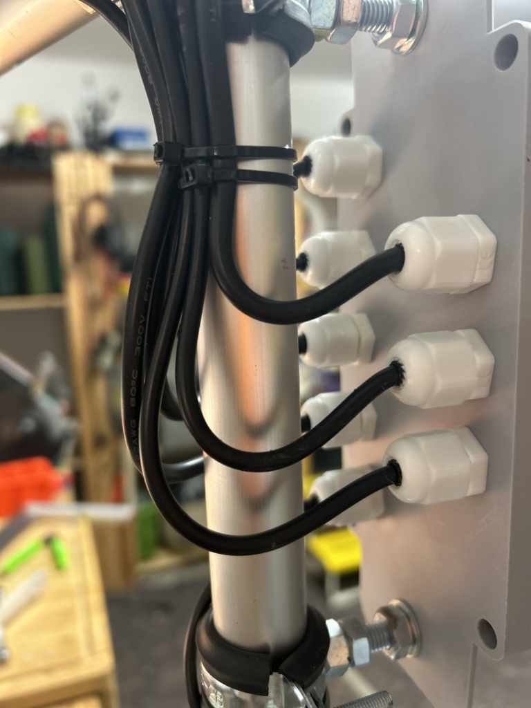
Then the cable is connected to the control unit at the terminals labelled “WindD”. Disconnect the control unit from the power supply first!
- WindD1: brown
- WindD2: black
- WindD3: blue
- WindD4: yellow

The control unit can now be supplied with power again. Now check once more whether the corresponding readings are displayed in the Devices tab. To do this, turn the sensor to different directions and check at task 10 (ads1115_1) whether the voltage value raw_winddir changes. Once the function test is complete, the assembly is already done!
