Introduction
Recording the amount of rain is part of every weather station. Automatic rain gauges usually use a tipping bucket: a two-part measuring chamber fills with rainwater and tips over at a certain fill level. The amount of precipitation is calculated from the number of tips, which are recorded electrically via a magnet and a reed contact.
For climatologically meaningful measurements, the rain gauge should be installed horizontally at an open location that is representative of the local climate (according to the DWD approx. 1 m above the ground). In practice, precipitation measurement is comparatively error-prone – measurement uncertainties of 10-20 % can hardly be avoided.
Available measurements
| Variable | Unit | Source | Description |
|---|---|---|---|
| rain_24h | mm | Measurement | Rain amount last 24 h |
| rain_daily | mm | Measurement | Rain amount current day |
| rain_event | mm | Measurement | Rain amount current event |
| rain_monthly | mm | Measurement | Rain amount current month |
| rain_weekly | mm | Measurement | Rain amount current week |
| rain_yearly | mm | Measurement | Rain amount current year |
| rainrate | mm/h | Measurement | Rain rate |
Sensor used
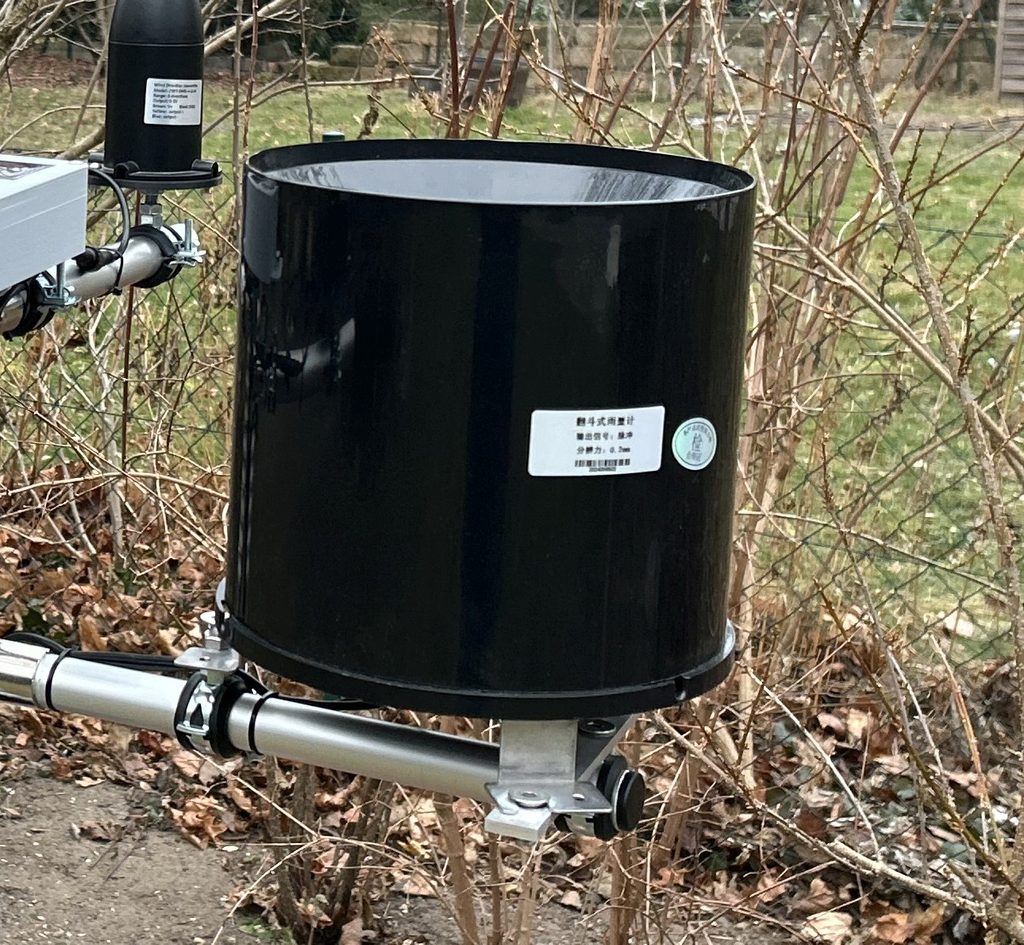
We use a tipping bucket rain gauge with pulse output (reed contact). It has a collecting area of Ø 200 mm (≈ 314 cm²) and measures 0.2 mm of rain per tip – a 0.1 mm variant is also available. The build quality is very good: robust bucket with good rain drainage, stainless steel sieve as protection against dirt and a large circular spirit level with levelling screws for exact horizontal alignment. The installed reed contact is a brand-name product (PS-3150) and can be bought as a spare part.
Datasheet
Specification
- Measuring principle: tipping bucket with pulse output (reed contact)
- Collecting area: Ø 200 mm (≈ 314 cm²)
- Resolution: 0.2 mm per pulse (selectable 0.1 / 0.2 / 0.5 mm)
- Accuracy: ≤ ±3 %
- Rain intensity: 0.01-4 mm/min (max. 8 mm/min)
- Output: pulse (used); additionally RS485, 0-2/0-5/0-10 V, 4-20 mA
- Reed contact: PS-3150 (available as a spare part)
- Housing: stainless steel 304 / ABS, integrated stainless steel sieve + spirit level
- Power consumption: ≤ 0.2 W
- Operating range: 0 … +70 °C, ≤ 100 % RH
- Dimensions: Ø 200 mm, height 233 mm
Parts list
Available as a kit
All necessary components of this guide are also available as a complete kit! The kit contains all individual components (except adhesives, solder, etc.) – including the required PCBs and 3D printed parts. With your purchase you also support us in the further development of the DIY weather station.
Request a kit ›| Quantity | Component | Source |
|---|---|---|
| 1 pc. | Aluminium flat bar 4×20×300mm (cross member) | Ali Express / Amazon / hardware store |
| 1 pc. | Rain amount sensor / tipping bucket (0.2 mm per pulse), Ø 200 mm | Ali Express / Amazon |
| 3 pcs. | Stainless steel countersunk screw DIN7991, M8×20mm | Ali Express / Amazon / hardware store |
| 1 pc. | Stainless steel countersunk screw DIN7991, M8×30mm | Ali Express / Amazon / hardware store |
| 4 pcs. | Stainless steel washer M8×16×1.5mm | Ali Express / Amazon / hardware store |
| 4 pcs. | Stainless steel hex nut M8 | Ali Express / Amazon / hardware store |
| 1 pc. | Cable gland IP68, PG07 (M12) | Ali Express / Amazon |
| 2 pcs. | Swivel pipe clamp, 25-28mm / 3/4″ | Ali Express / Amazon / hardware store |
| 4 pcs. | Cable ties 3×150mm, UV-resistant | Ali Express / Amazon / hardware store |
Required tools and consumables
- Drill
- 8 mm steel drill and 16 mm countersink (alternatively 14-16 mm drill)
- Saw and file for cutting the aluminium flat bar to length
- Wrench / Allen key (M8)
- Spirit level if necessary (in addition to the built-in spirit level)
- Adhesive (all-purpose adhesive)
Assembly instructions
Mount the control unit first
This guide assumes that you already have a working control unit! So, if necessary, start with the control unit before assembling this sensor module.
First, the aluminium flat bar is prepared as a cross member: the bar is cut to a length of 240 mm. Use a fine metal saw for this – aluminium is very easy to work with. Deburr the edges with the file. Then drill two 8 mm holes into the flat bar at a distance of 200 mm (i.e. 20 mm from the outer edge each) as well as an 8 mm hole exactly in the middle. Then chamfer all 3 holes with the countersink for the countersunk screws.

The flat bar is attached to the mounting system (mast) with a swivel pipe clamp. To do this, attach the bar in the middle to a clamp with a 20 mm M8 screw and lock it to the mounting system.

The middle sensor foot is attached directly to the mast with a pipe clamp – for this, use the 30 mm countersunk screw with two lock nuts, which allow the sensor to be levelled exactly in height later.

The two outer sensor feet are screwed tightly to the aluminium flat bar (M8 countersunk screw, washer, nut).


There is a large circular spirit level in the base of the sensor for alignment. Use the spirit level to align the rain gauge exactly horizontally. This is very important to achieve good measurement results.

The supplied stainless steel sieve is mounted at the top of the collecting funnel as protection against dirt (adhesive).
The cable is now routed neatly down to the control unit (note: the cables should only be fixed with cable ties once the assembly of the entire weather station has been completed – this way cables can be bundled). The cable is fed into the control unit with a downward loop. This ensures that dripping water that collects on the cable is directed away from the cable gland. The cable is shortened accordingly and stripped for approx. 10 cm inside. This leaves enough reserve for routing.
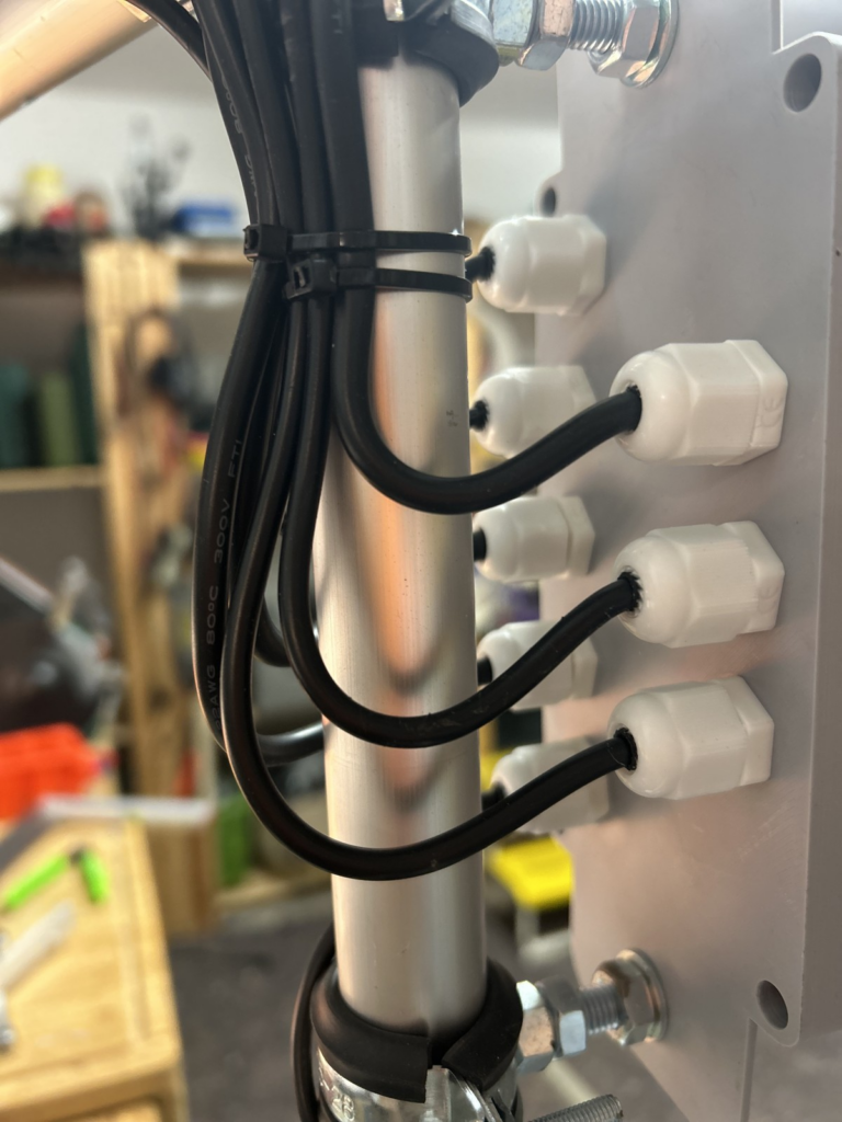
Then the cable is connected to the control unit at the terminals labelled “RainA”. Disconnect the control unit from the power supply first!
- RainA1: red
- RainA2: black

The control unit can now be supplied with power again. Now check once more whether the corresponding readings are displayed in the Devices tab. To do this, tip the bucket on the sensor back and forth every 2-5 seconds and check at task 1 (input_1) whether the value raw_rainrate changes. Once the function test is complete, the assembly is already done!